Design Capability
Production Capacity
Quality Control
LATEST PRODUCTS
PRODUCT
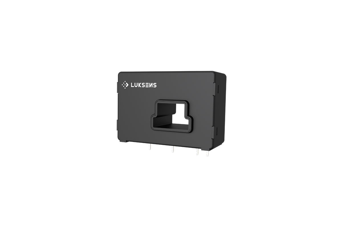
N2002P Close-Loop current sensor
N125P Close-Loop current sensor
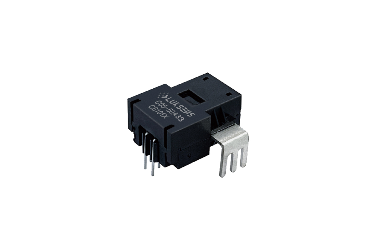
N1252H Close-Loop current sensor
N125H Close-Loop current sensor
N1002H Close-Loop current sensor
N100H Close-Loop current sensor
N502H Close-Loop current sensor
NxxNEP Close-Loop current sensor
N50H Close-Loop current sensor
NxxA Close-Loop current sensor
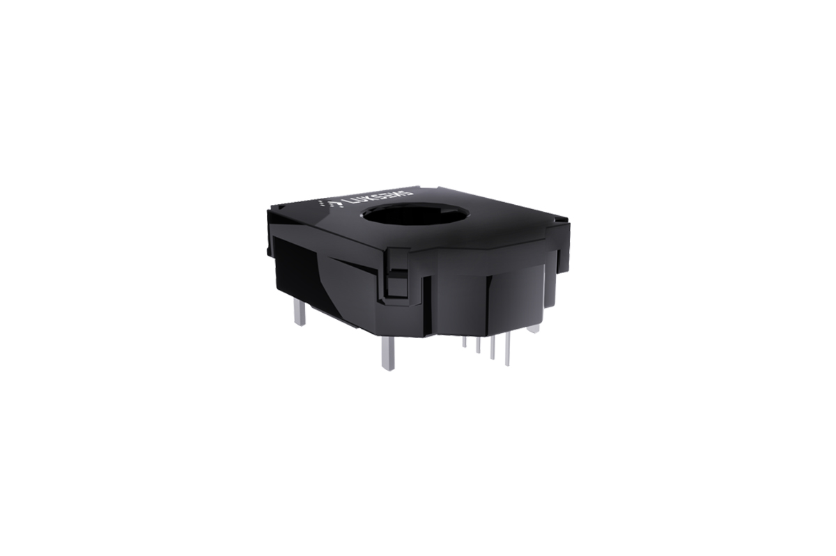
N25A Close-Loop current sensor
Types of Current Sensors and Their Features
Nowadays, in industrial equipment, current detection usually requires isolation measures. There are many different current sensor suppliers that manufacture the current sensor by various methods. The methods include shunt resistance + isolation op amp/isolation ADC method (shunt resistor+isolation amplifier/isolation ADC), core current sensor method (open-loop, close-loop, fluxgate) and coreless current sensor method (general coreless, AKM).
This page will provide an overview of the various current sensing methods and what we offer as experienced current sensor manufacturer.
1. Shunt resistance + isolation op amp/isolation ADC method
The shunt resistance + isolation op amp/isolation ADC method is to flow the measured current through a known resistor, and calculate the current value according to the drop voltage value of the resistor. Insulation measures need to be implemented by using edge amplifiers or ADCs in the back-end. This is one of the methods used by some of current sensor suppliers.
This method is a wide-used current detection method and is suitable for detecting small currents that do not need to worry about heating. However, in applications in which large currents (10A or more), the following disadvantages are more pronounced:
1) As there are many components on the primary side (high voltage side) such as isolated power supplies and bipolar power supplies, the design takes time and effort.
2) As the heat generation is proportional to the resistance value, the heat generation is several times to several tens of times of other methods, which makes the heat dissipation design difficult.
3) Due to the large number of parts, wiring is difficult and the mounting area increases.
There is a way to work around the shortcomings of the shunt resistor + isolating amplifier/isolating ADC approach described above, named a magnetic current sensor.
2. Magnetic Current Sensor
Magnetic current sensor detects the amount of current by using a magnetic sensor to detect a magnetic field generated around an energized current line.
Unlike the shunt resistance method, the magnetic current sensor has an insulating structure inside, so there is no need to install an insulating amplifier or an isolated ADC in the rear stage.
In addition, as there is no need to change the resistance value according to the amount of current, it is an excellent solution that can solve the disadvantage of the shunt resistance method that can only detect the current with a low resistance resistance. This is also a wide-used method by current sensor suppliers.
2.1 Coreless Current Sensor
The coreless current sensor is a current sensor with a very simple structure that does not use a magnetic core to detect the magnetic field generated by the energized current of the primary conductor, but directly detects it by a Hall element and amplifies and corrects its output voltage by an IC, which used by some of the current sensor suppliers.
It can solve the problems caused by the magnetic core while maintaining the advantages of current sensors with a core, and has been used since 2010 in applications that emphasize size miniaturization.
However, silicon Hall elements have low sensitivity, so for compensation, some measures must be taken, such as thinning the primary conductor to increase the magnetic field strength, or increasing the gain of the correction IC. There are several advantages and disadvantages.
2.1.1 Advantages
1) As there is no magnetic core, the height can be reduced. Simple internal structure, easy to reduce cost;
2) There is no magnetic core, so there is no hysteresis error;
3) Low current consumption
2.1.2 Disadvantages
1) Since the primary conductor becomes thinner and the resistance value becomes higher, it is easy to generate heat. Large currents cannot be measured;
2) The sensitivity of the Hall element is low, and the frequency band is designed to be narrow in order to obtain sufficient resolution. Therefore, the response time becomes longer;
3) Increasing the gain of the correction IC also amplifies the offset of the Hall element, making it difficult to improve accuracy.
The solution to the above shortcomings of the coreless current sensor is to use a cored current sensor which is what we offer as current sensor supplier.
2.2 Cored Current Sensor - what we offer as experienced current sensor manufacturer
In magnetic current sensors, sensors that use a magnetic core to collect and detect the magnetic field around the current line are called cored current sensors.
Core current sensors can be divided into three categories: 1) Open-loop type, 2) Closed-loop type, 3) Fluxgate type, which is what we offer as experienced current sensor manufacturer.
2.2.1 Open-loop Type Current Sensor
Open-loop Type Current Sensor consists of three main components: an accurate low temperature drift linear hall sensor, a flux collector, and a current transformer. It offers markedly low resistance, reducing power loss and temperature drift to deliver exceptional performance.
2.2.2 Closed-loop Type Current Sensor
Closed-loop Type Current Sensor is a current sensor which operates on the principle of magnetic compensation. It measures DC, AC or pulse currents and their combinations, with galvanic isolation techniques used to separate the primary and secondary circuits.
2.2.3 Fluxgate Type Current Sensor
A fluxgate type current sensor incorporates dynamic fluxgate detection technology. Its design is simple and practical, with the ability to inhibit high temperature drift. Fluxgate technology makes use of the phenomenon of magnetic core saturation to modulate the measured magnetic field, transforming it into an electric field and thus, completing the magnetic field measurement process.
2.2.4 Comparison
Price from low to high: Open-loop type < Closed-loop type < Fluxgate type
Accuracy from low to high: Open-loop type < Closed-loop type < Fluxgate type
2.2.5 Disadvantages and Advantages
Disadvantages
1) As there is magnetic core material inside the cored current sensor, it is difficult to reduce the height and the installation position is limited;
(But Luksens can produce compact size current sensors as experienced current sensor manufacturer)
2) Since the core has hysteresis in principle, the sensor output (bias voltage) at zero current changes before and after applying a large magnetic field, which causes errors.
(But Luksens makes it nearly zero as experienced current sensor manufacturer)
Advantages (what we offer as experienced current sensor manufacturer)
1) Large currents can be measured;
2) Output voltage proportional to carried current;
3) Compact size for PCB mount;
4) Accurately measures AC, DC and pulse currents;
5) Nearly zero offset voltage;
6) High frequency bandwidth;
7) Rapid response; minimal noise output;
8) Superior temperature stability and linearity;
9) No insertion losses;
10) Nearly zero magnetic hysteresis;
11) Excellent current overload capacity.
2.2.6 Applications
Our current sensors can be applied on many areas as experienced current sensor manufacturer, such as Automotive Battery Management, EV Chargers, Automotive Motion Control, Smart Grid, Welding, Automation, Drives, Power Supplies, Renewable Energies etc..
1) For example, in terms of renewable energies, as the use of power electronics is a must to drive and control energy from renewable sources in the most energy-efficient way. Modern systems require precise coordination between the power semiconductors, the system controller, mechanics and the feedback sensors. Current sensors provide the necessary information from the load to fulfil that function.
Hence, current sensors is a indispensable parts in many areas. And Luksens is your specialist for current sensor solutions. We are an experienced current sensor manufacture.
FAQs
The Hall Effect is the presence of a voltage when an external, perpendicular magnetic field is applied to a current carrying conductor. The conductor, or the Hall Element, is biased with a constant current. As magnetic field changes, a change in voltage across the hall element occurs. This voltage can then be amplified and conditioned to provide an output that is related to the magnetic field. Using this principle, magnetic field can be concentrated perpendicular to the hall element using integrated packaging, ferromagnetic cores, or coreless busbars. There are many current transducer manufacturers using this principle, as Hall effect current sensors have the advantage of inherent isolation, low power loss, and stability across temperature while providing an analog output voltage that can be monitored by a micro-controller. And it is what we provide as professional current transducer manufacturer.
There are different current sensors in the market, provided by currenr sensor suppliers. Basically every shunt solution can be replaced with an integrated Hall-effect sensor, simply by routing the current traces through the integrated current sensor rather than through an external shunt. The few shunt solutions that may not be practical for integrating Hall-effect sensors include ultra-low current resolution (in uA) or ultra-high speed (>1Mhz).
The main benefits of switching from a shunt solution to an integrated Hall-effect solution are increased isolation, reduced layout size, and reduced design complexity. The common-mode voltage of most shunt solutions cannot exceed 100 V without using an isolation amplifier that requires an external isolation circuit. Compare this to Hall-effect current sensors, which provide inherent isolation from the current path to the signal pins. Switching to Hall-effect sensors also eliminates the need for external shunts and input filtering. This reduces layout space and design complexity. If you are interest, feel free to email us. We can definitely provide you the solution as professional currenr sensor supplier.
Parts can be proportional or non-proportional. The ratio indicates that the device sensitivity is proportional to the device supply voltage VCC. Additionally, the device’s output at 0 A, also referred to as V IOUT(Q), is nominally equal to vcc /2. The VIOUT(Q) and sensitivity values for non-ratiometric devices are stable over changes in VCC over the specified input voltage range. The ratio method is useful when the sensor input voltage is on the same line as the ADC reference voltage. Non-proportional components are useful in applications where the sensor input voltage is noisy or unstable. If the part is ratiometric, an unstable V CC will produce a noisy output.
It is the maximum current draw of the sensor electronics at the specified supply voltage when the primary signal is zero, plus the secondary current IS. This parameter only applies to sensors with current output.
As experience current transducer manufacturer, within 2 months if the customized samples are developed based on the existing product platform. For standard models, it would be 4 to 6 weeks.